news

Look at the design page for info on the plywood velomobile construction.

Tuesday 9 October 2012

break down!

This morning the body failed. Yesterday I stiffened the spring. While taking a put hole the spring support broke. The connection to the circular sheet in front was cracked a few weeks ago. I should have done something about it then....
The connection in front was failed already a few weeks ago.

When the spring lost support the wheel damaged the body.


Monday 8 October 2012

PU foam spring failed

The PU foam spring of the left McPherson strut was failed. The right side is ok. It could be the material is degraded after 20 years. Maybe the wall thickness is too small. The cylinder shape buckles outward. Every time I take a right turn the wheel touches the wheel box. I have fixed it today by wrapping cotton tape around it to prevent the cylinder from buckling.


The recess on top fits in a hole in the wooden body. A aluminium tube glides in this 'bearing'.


Saturday 6 October 2012

rear light

In June I started a new job at Holmatro in Raamsdonksveer 20 km from were I live. I never planned to use the prototype of the plywood velomobile for my daily commuting but the delivery time of a Quest XS is 6 months... It 's no use to order one as it will arrive in the spring.

In the summer I used my MTB but now the wetter is getting poor I'm forced to use the prototype. I must have travelled overr 400 km now and without structural problems (apart from a broken seat hook and a chain that sprung of the idler wheel). I see some cracks here and there but nothing serious (I think). The prototype was designed on the edge (and over it here and there) to learn. I have mixed feelings when I drive over a rough road with put holes in the morning. The idea of having to call my new colleagues when I'm stuck is worrying me. But so far so good...

What I don't like: getting in and out is a burden. The chain is noisy. The Rohloff is very noisy in low gears (it is directly bolted to the monocoque). The velcro of the tent isn't strong enough, the seat is just a piece of cloth hanging like a beach chair and this gives little support to my middle back. I improvised with little hooks here and there and it is very irritating that I get hooked too now and then. When I take really hard turns the steering get uncontrolled a bit. Sometimes the chain tube bounces to the right crank. I enlarged the front wheel box at the right side because the wheel would hit it while steering. The left spring is too soft and in right turns the wheel hits the top of its box (~ 2 mm has been grinded away already!).

It is getting dark in the morning so I have installed a LED rear light. I use a head light too. Hope I'm visible now.
LED rear light. Nice looking place but I expect it will become very dirty when it rains...
Johan Goosens called me and mentioned there may be interest from Belgian high schools in the plywood velomobile project. I really hope this design inspires other people. There is a lot to be improved.

Sunday 23 September 2012

Une voiturette a pedales

Look what Cedric Doutriaux send me. Two seater, rear wheel steering, front wheel drive, 40 kg, wood and paper. From the inter bellum I think.


Saturday 8 September 2012

Velomobile Seminar 2012

It was an interesting seminar. I liked best the work of Harald Meckenburg, Pieter Hollebrandse and Miles Kingsbury. I was very happy to meet people that have experience with sustainable alternatives for epoxy and hope I can soon put links to their work on this blog (Please send me your info!).

Patrick Hagemann showed me a wooden rim that was glued with a caseine based adhesive that you can make yourself. This movie shows how Patrick makes a wooden rim:


The chairman of the Dutch HPV association (Kees van Malsen) mentioned that he would try to organize a seminar in a few years from now. The proceedings will be available from the velomobile seminar website. 
Erik Marynissen

Erik Marynissen has milled the part for the wheel cover with his gigantic homebuilt router. Thank you Erik!

I have tacked the parts to a curved (~R 600 mm) piece of wood and glued them together with PU construction glue (Pattex PU construct).


one segment

tack and glue
the wheel cover is almost a sphere segment

sorry for the terrible photo

Friday 17 August 2012

Csiro electric motor

This in wheel motor is reported to have an efficiency of 98%. I would love to have one for my velomobile...


Doughnut-shaped object wound about with brightly coloured wire.
The stationary coil

Sunday 12 August 2012

seminar presentation

On Friday September 7 I will present the plywood velomobile at the 7th velomobile seminar  2012 in Dronten, the Netherlands. I will bring the prototype and, within reason, it is possible to make a test ride (The condition is that everything that you break you fix too). I have prepared a power point presentation and am open to your suggestions. Come to Dronten!

down load the power point to see it !

Monday 30 July 2012

Jig saw puzzle connection !

paper model
I think have found a new way to make (or approximate) compound curved shapes with flat sheet. Plywood material is flexible and can be deformed to a compound curvature. On my computer I have modelled a spherical wheel cover consisting of 7 pieces. They will be connected with jig saw puzzle joints. I have deformed the piece on the computer to a flat plate. The picture shows a paper model. I hope to present a model in plywood soon. The jig saw puzzle joint can be produced easily with laser cutting machines and I expect the assembling with some glue is easy too.
Easy connecting with the jig saw puzzle connection. The curved sides will deform the flat plate into a sphere segment.

Summerlab was OK

I presented the plywood velomobile to on the Summerlab in Nantes. Watch the video. We tested the machine. The seat, the front suspension, the soft top and the chain guidance were failed or considered inadequate and than repaired and improved. Thank you guys!

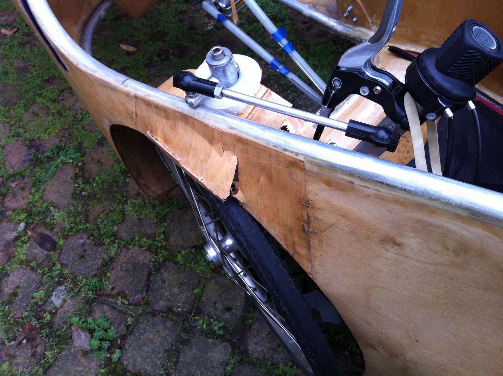
We have thought about how the plywood sheets can be attached. Below you see a sample.

provisionally attached with staples...

glued with wood construction glue (foaming PU)

will we ever get these staples out again?
To get experience we tried to make a hard top too.


The chain is guided by four toothed chain wheels to reduce the losses up to the max. But it would easily derail from the rear sprocket because it could not be tensioned properly.
Jacques and ? (sorry I forgot your name) are adapting the wheel mount so the chain can be tensioned properly
Joris wanted to make a one wheeled trailer (remorque). I showed him my plywood design. Building a simple trailer was a fine way to learn (developing the sheet, bending the alu tube... )


Joris has made a mock-up to evaluate the shape and generate the development of the sheet


unwrapping the sheet
The edge at the top of the trailer will be reinforced with a tube. Bending it is not so easy. Because we did noty compensate for the elastic relaxation the tube did not get its definitive form directly...

bending aluminium tube Dxt 18x1

for the last turn we fix at a new position the tube so we can release the first par


oops ! We should have filled it with sand...
But not only details were studied. Scale models and a 1:1 mock-up was made too:


On the wiki you will find some more !

The summerlab was a very pleasant gathering of interesting people and thoughts. Although not presented at the summerlab and already written in 2004 to me the most intriguing was the philosophy on cyborgs of Natasha Roussel.

Thursday 17 May 2012

S Eco Marathon

Today I visited the S Eco Marathon in Rotterdan. 3000 students united in 200 teams trying to get as far as they can on one liter gasoline...  It was a great pleasure to discover that the winner of the 2003 competition was a wooden monocoque. It was a team of the St Joseph La Joliverie from Nantes, France. They reached 3103 km. Come to Nantes this summer

The 2003 winner LPTI St Joseph La Joliverie

The 2003 winner LPTI St Joseph La Joliverie

detail of the wooden body

Sunday 8 April 2012

Summer lab à Nantes

Check this out: July 23 to 28 plywood velomobile summerlab and this too in Nantes.

Please let me know if you are coming to build your own plywood velomobile. Provided enough people come I will be there and bring my proto.

The second proto of a plywood velomobile

Friday 9 March 2012

K-drive

The HPTeam Delft and Amsterdam  choose the K-drive to improve their machine. This video shows the K-drive. I found this redesign on the web. I like the toothed belt: light and clean.

LucaBike redesigned the K-drive

Saturday 28 January 2012

On mass and aerodynamics

Is there a trade off between mass and aerodynamics? A streamlined velomobile may reach a higher speed at the same power input because of the decreased aerodynamic drag but the fairing adds extra mass to the vehicle. Is there a speed penalty in adding mass? The rolling resistance of the wheels will increases but also the time and energy needed to accelerate the vehicle. While setting a new hour record only the first minutes are used for increasing the speed. But in normal every day traffic we may have to stop every km...
I calculated the total trip time for a 5 km trip and varied the number of starts. In the next diagram you find the total trip time and the maximum speed for different vehicles. The coefficient of rolling resistance was held constant at 0.005. The QuestSL is a Quest with the mass of an MTB. For the calculation of the plywood velomobile I estimated the effective area to be equal to that of the Versatile. The mass of the Plywood Velomobile was very optimistic chosen to be 18 kg (The current proto is 23 kg).
.

I assumed a cyclist that delivers 75 W power. At that level the MTB would reach ~20 km/h which is more that the most of us do... We can conclude that at 7 starts in 5 km the Quest and the Plywood Velomobile perform equal. The mass reduction compensates for the compromised aerodynamic quality. At an increased cyclist power the break even point moves to the right. 7 starts in a 5 km trip is quite high but not unrealistic for an urban trip. 
All in all we can conclude the most apparent difference exists between the MTB and the other vehicles. The differences between the velomobiles are small. It would be interesting to see what happens when a small slope is taken into account. Another interesting thing is recuperative breaking and start assist.

On second thougth: After a 5 km trip in a Quest with one start only the total work done is 48.2 kJ. The Quest reaches a maximal speed of ~42 km/h after 3.5 minutes. The kinetic energy of the vehicle and rider at 42 km/h is ~7 kJ. Now it becomes very clear what happens when we have to stop and accelerate again: we loose the kinetic energy of 7 kJ which is 7/48=15 % of the energy needed with one start only. Would we have to stop 7 times our energy usage more than doubles ! The MTB uses 104 kJ for the 5 km trip with one start only.  His kinetic energy reaches 2 kJ only (2/104= ~ 2%). An extra stop doesn't bother him to much... 
Depending on the number of starts in our trip, recuperative breaking and start assist would give a significant increase in performance of the Quest...

Remark: decreasing the mass of the velomobile is not helping much as it is dominated by de rider.

Wednesday 18 January 2012

Cycloid drive


Miles Kingsbury reports a 90% efficiency on his cycloid drive:

"We have also found that although the drive is mechanically very efficient, physiologically it was not so good. We did a number of tests and found it was only about 90% as efficient as a circular drive. In the end we decided this inefficiency was caused because the main leg muscles were performing a 50% duty cycle compared with only about half that on a circular drive. Although it seems that this higher duty cycle should help efficiency, it doesn’t allow the muscles to recover and get rid of lactic acid build up, causing a severe burning sensation! ".

I will try to make a multi body analysis of this drive. It may be the problem is the kinetic energy of the thigh, calf and foot at the extreme positions. The cyclist has to do work for decelerating and accelerating his legs at the returns.

A page of Human Power, the technical journal of the IHPVA issue Volume 8 No2, spring 1990

Saturday 14 January 2012

Lineair drive

The conventional pedal rotates around the crank axle. In a velomobile with rotating pedals the feet are not only moving in driving direction but also up and down. Should the up and downwards motion be done away with the nose of the velomobile could be much lower. That may improve the aerodynamics of the body.

multi body of a human leg
Instead of a rotating crank we could use an oscillating crank. The pedals would move for and backwards while the crank rotates 60º only. The cranks could be connected via 2 sprag clutches to the wheels. But than the pedal speed would be almost constant. Only at both extreme positions the pedal speed would have to change very fast to the opposite direction. Is that comfortable and efficient?
motion of center of gravity of thigh, calf and foot [m]
To get an impression about the losses that could be created I calculated the kinetic energy of the thigh, calf and feet of a human leg while driving the lineair drive. At the returning positions they are 2 and 5 Joule. The last value is when the leg is stretched. Humans (animals too) are able to optimize their motion. It could be that we would stretch out our foot in the last phase to reach the most stretched leg position. In that case the kinetic energy of the thigh and calf would be recuperated. I think this is what we do while we are running.
kinetic energies Et: translation, Er: rotation
But in the most pessimistic approach all kinetic energy would get lost: 7 Joule at every stroke. At a normal frequency of 1.5 Hz that would amount up to 2*7*1.5=21 Watt. That is an enormous  amount. A normal bicyclist produces 75 to 150 Watt! It may be that the foot motion has to be decelerated and accelerated in a controlled way at the returns. This kind of loss may exist in the rowing bike too. Is there anyone out there who has done experiments with lineair drives? Paul Jaray developed a similar drive in 1920. Miles Kingbury developed an interesting alternative: the K-drive. The Human Power-team is experimenting with it too.